Altera DE0 - Nano開發 ADC應用
前言:
最近因為做實驗的關係,作者接觸了Altera DE0-nano開發版,發現這個板子雖然小小一塊但功能卻很齊全的,包含了加速計、8個led燈示、四段指撥開關、兩個復歸按鈕、8通道12bitADC以及多達80個GPIO(裡面涵蓋Vcc及Gnd)可以去使用,而本文章是使用其ADC讀取感測器數值的應用本文章是使用其ADC讀取感測器數值的應用
下圖為板子的正反面照片,ADC位置在背面(圖b)
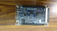


圖a. 正面照 圖b. 背面照

圖c. Pin腳圖
DE0-Nano使用的ADC晶片為ADC128S022,其通訊使用的是SPI進行資料交換如下圖所示

圖d. ADC128S022 Serial Timing Diagram
依據圖d的通訊圖可以看出當CS Low時,其SCLK以16個為一組DATA的資料,為了配合撰寫程式,本文章以0至15來取代1至16,其中資料的第0個與第1個不列入參考,而第2~4為選擇ADC Channel的Address(由Din腳為提供),最後第4~15為晶片所量測到的電壓數位訊號(由Dout送出),其訊號範圍為0~3.3伏特(數位訊號為0~4095)。
實作:
SCLK:
library ieee;
use ieee.std_logic_1164.all;
use ieee.numeric_std.all;

entity Divider100 is
 generic (
  CLK_DIV : integer := 100
 );
 port(
  reset: in std_logic;
  CLK : in std_logic;
  enable : in std_logic;
  SCLK_RISING : out std_logic;
  SCLK_FALLING : out std_logic
 );
end Divider100;

architecture arch of Divider100 is
 signal sclk_r, sclk_f : std_logic;
 signal counter : integer range 0 to CLK_DIV;
begin
 process(CLK, reset)
 begin
  if(reset = '0') then
   sclk_r <= '0';
   sclk_f <= '0';
   counter <= 0;
  elsif(rising_edge(CLK)) then
   if(enable = '1') then
    if(counter = ((CLK_DIV/2)-1)) then
     sclk_r <= '0';
     sclk_f <= '1';
     counter <= counter+1;
    elsif(counter = (CLK_DIV-1)) then
     sclk_r <= '1';
     sclk_f <= '0';
     counter <= 0;
    else
     sclk_r <= '0';
     sclk_f <= '0';
     counter <= counter+1;
    end if;
   else
    sclk_r <= '0';
    sclk_f <= '0';
    counter <= 0;
   end if;
  end if;
 end process;
 SCLK_RISING <= sclk_r;
 SCLK_FALLING <= sclk_f;

end arch;
SPI_Out
library ieee;
use ieee.std_logic_1164.all;
use ieee.numeric_std.all;

entity SPI_Out is
 port(
  reset : in std_logic;
  CLK : in std_logic;
  enable : in std_logic;
  update :in std_logic;
  dataStep :in integer;
  pinSelect : in std_logic_vector(2 downto 0);
  divider_r: in std_logic;
  divider_f: in std_logic;
  SPI_CS : out std_logic;
  SPI_MOSI : out std_logic;
  SPI_SCLK : out std_logic
 );
end SPI_Out;

architecture arch of SPI_Out is
 signal outputTemp : std_logic_vector(2 downto 0);
begin
 process(CLK, reset)
 begin
  if(reset = '0') then
   outputTemp <= (others=>'0');
   SPI_CS <= '1';
   SPI_MOSI <= '1';
   SPI_SCLK <= '1';
  elsif(rising_edge(CLK)) then
   SPI_CS <= not enable;
   if(update = '1') then
    outputTemp <= pinSelect;
   end if;
   if(enable = '1') then
    if(divider_r = '1') then
     SPI_SCLK <= '1';
    elsif(divider_f = '1') then
     SPI_SCLK <= '0';
    end if;
   else
    SPI_SCLK <= '1';
   end if;
   if(divider_f='1') then
    case dataStep is
     when  2  => SPI_MOSI <= outputTemp(2);
     when  3  => SPI_MOSI <= outputTemp(1);
     when  4  => SPI_MOSI <= outputTemp(0);
     when others => NULL;
    end case;
   end if;
  end if;
 end process;
end arch;
SPI_In
library ieee;
use ieee.std_logic_1164.all;

entity SPI_in is
 port(
  reset : in std_logic;
  CLK : in std_logic;
  dataStep :in integer;
  update :in std_logic;
  SPI_MISO : in std_logic;
  dataOutput : out std_logic_vector(11 downto 0)
 );
end SPI_In;

architecture arch of SPI_In is
 signal misoSignal : std_logic;
 signal outputTemp : std_logic_vector(11 downto 0);
begin
 process(CLK,reset)
 begin
  if(reset = '0') then
   misoSignal <= '0';
   outputTemp <= (others=>'0');
  elsif(rising_edge(CLK)) then
   misoSignal <= SPI_MISO;
   if(update = '1') then
    dataOutput <= outputTemp;
   end if;
   case dataStep is
    when  4  => outputTemp(11)  <= misoSignal;
    when  5  => outputTemp(10)  <= misoSignal;
    when  6  => outputTemp( 9)  <= misoSignal;
    when  7  => outputTemp( 8)  <= misoSignal;
    when  8  => outputTemp( 7)  <= misoSignal;
    when  9  => outputTemp( 6)  <= misoSignal;
    when 10  => outputTemp( 5)  <= misoSignal;
    when 11  => outputTemp( 4)  <= misoSignal;
    when 12  => outputTemp( 3)  <= misoSignal;
    when 13  => outputTemp( 2)  <= misoSignal;
    when 14  => outputTemp( 1)  <= misoSignal;
    when 15  => outputTemp( 0)  <= misoSignal;
    when others => NULL;
   end case;

  end if;
 end process;
end arch;
SPI_Master
library ieee;
use ieee.std_logic_1164.all;
use ieee.numeric_std.all;
use work.Bus_Declare.all;

entity SPI_ADC_Master is
 port(
  CLK : in std_logic;
  reset : in std_logic;
  enable : in std_logic;
  SPI_MISO : in std_logic;
  SPI_MOSI : out std_logic;
  SPI_CS : out std_logic;
  SPI_SCLK : out std_logic;
--  outputLed : out std_logic_vector(7 downto 0);
  dataOutput : out bus_array_12(7 downto 0)
 );
end SPI_ADC_Master;

architecture arch of SPI_ADC_Master is
 signal outputTemp : bus_array_12(7 downto 0) := (others => (others => '0'));
 signal dataStream : std_logic_vector(11 downto 0);
 signal updateSignal : std_logic;
 signal sclk_r_Signal : std_logic;
 signal sclk_f_Signal : std_logic;
 signal dataStepSignal : integer;
 signal pinSelect : std_logic_vector(2 downto 0);
 signal tempCount : integer := 0;
 component Divider100 is
  port(
   reset: in std_logic;
   CLK : in std_logic;
   enable : in std_logic;
   SCLK_RISING : out std_logic;
   SCLK_FALLING : out std_logic
  );
 end component;

 component SPI_In is
  port(
   reset : in std_logic;
   CLK : in std_logic;
   dataStep :in integer;
   update :in std_logic;
   SPI_MISO : in std_logic;
   dataOutput : out std_logic_vector(11 downto 0)
  );
 end component;

 component SPI_Out is
  port(
   reset : in std_logic;
   CLK : in std_logic;
   enable : in std_logic;
   update :in std_logic;
   dataStep :in integer;
   pinSelect : in std_logic_vector(2 downto 0);
   divider_r: in std_logic;
   divider_f: in std_logic;
   SPI_CS : out std_logic;
   SPI_MOSI : out std_logic;
   SPI_SCLK : out std_logic
  );
 end component;

 component StepCounter is
  port(
   reset : in std_logic;
   CLK : in std_logic;
   enable : in std_logic;
   update : out std_logic;
   divider_r: in std_logic;
   divider_f: in std_logic;
   dataStep : out integer
  );
 end component;
begin
 DIVIDER: Divider100 port map(reset, CLK, enable, sclk_r_Signal, sclk_f_Signal);
 SPIIn : SPI_In port map(reset, CLK, dataStepSignal, updateSignal, SPI_MISO, dataStream);
 SPIOut : SPI_Out port map (reset, CLK, enable, updateSignal, dataStepSignal, pinSelect, sclk_r_Signal, sclk_f_Signal, SPI_CS, SPI_MOSI, SPI_SCLK);
 STEPCOUNT : StepCounter port map(reset, CLK, enable, updateSignal, sclk_r_Signal, sclk_f_Signal, dataStepSignal);


 process(CLK, reset)
  constant pinCount : integer := 7;
 begin
  if(reset = '0') then
   tempCount <= 0;
   pinSelect <= "000";
   outputTemp <= (others => (others => '0'));
  elsif(rising_edge(CLK)) then
   if(enable = '1') then
    if(updateSignal = '1') then
     outputTemp(tempCount) <= dataStream;
     case tempCount is
      when  4  => pinSelect <= "000";
      when  5  => pinSelect <= "001";
      when  6  => pinSelect <= "010";
      when  7  => pinSelect <= "011";
      when  0  => pinSelect <= "100";
      when  1  => pinSelect <= "101";
      when  2  => pinSelect <= "110";
      when  3  => pinSelect <= "111";
      when others => NULL;
     end case;

     if(tempCount < pinCount) then
      tempCount <= tempCount + 1;
     else
      tempCount <= 0;
     end if;
    end if;
   else
    pinSelect <= "000";
    outputTemp <= (others => (others => '0'));
    tempCount <= 0;
   end if;
  end if;
 end process;

 dataOutput <= outputTemp;
end arch;
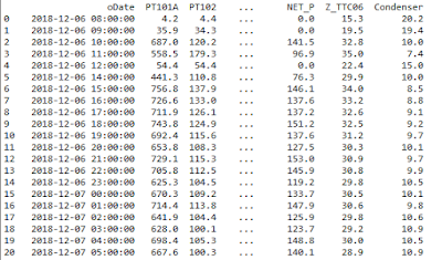
根據SPI_ADC模組中Channel0~Channel7皆會去掃描後將各個channel數值記錄在暫存器中,而下一章會教如何將數值傳出做應用
你好,我对这篇文章很感兴趣,因为我目前也在研究 FPGA。
回覆刪除你可以详细给我看看你所研究或了解到的内容吗?